
Front 4-Link Garage Alignment
December 3, 2022 By Nick Viggo

We start with just some general assembly. Nothing really super exciting here. However a brief rundown of what we did. We will install new bushings on the axel for the lower control arms. I also bought a pan hard bar because I am pretty sure that this won’t align correctly without some adjustment. We fitted the lower and upper control arms and the new pan hard bar. and roughed the alignment for the lower control arms. We put the new one piece axle in on the passenger side doing away with the center axle disconnect. We stuffed the old drivers side axel back into the drivers side. Hub assembly, rotors and brakes. Most of all the big stuff is back together.
Alignment time!
Alright so this isn’t a full alignment that you would get off alignment rack, It will get you damn close. I have been doing this for some time now and I’m not seeing any weird tire wear or any bad handling characteristics. I drive all over town on the highway then to the dirt and back. I would recommend taking your rig to alignment shop if you do more asphalt than dirt to maximize tire life.
Step one, we will make the front lower control arms straight in the chassis. I do this by using a second type of laser that shoots a beam across. Set laser on floor and align to, two points on the chassis that are the same at both sides. Yes the cross member is not perfect and can mount in ever so slightly different positions. I’m not to worried about it because this will get us extremely close. This will show the principle and I’m presuming that this rig will mostly live offroad so I don’t know that it need to ever need be better than that. We will see during testing.


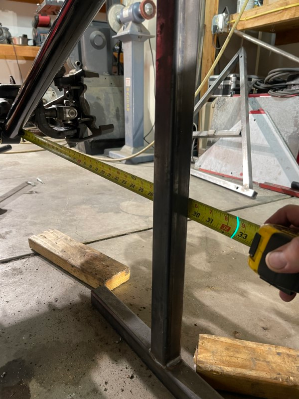
Now we take a tape measure and measure from the back of the front part of the control arm to the laser beam.
Measure from the same place on both sides. I used the mount for the lower control arm, this is drivers side. Here we see ~31″
Depending on your style of control arm you may not need to disconnect anything to make the adjustment however these are bushings on the axel end and a heim at the uni-rail end. I will have to remove the heim end and run the threads in or out to make the adjustment. How much thread can we adjust out? Well I prefer to thread in just as much as I can. however you need to be able to make some adjustments so I’m pretty comfortable with having at least as much threaded in as the thickness of the shank. So 1.25″ shank absolutely no less than 1.25″ threaded.
Passenger side come in at ~33.25″
passenger side after adjustment.
I made adjustment to make 32.5″ on the drivers side as well
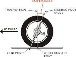
Now we will attach the upper control arms. I set caster to about 6 degrees. To be clear that’s 6 deg off level. Meaning both upper and lower ball joints are straight up and down from each other (True Vertical). We set the upper ball joint 6 deg behind the lower ball joint this will give the caster effect and make the steering wheel want to self straighten. Think of the front Wheels on a shopping cart. Now this will likely change when we go set up the drive line angle there may be a compromise. or even a transfer case drop.
Now that control arms are done we need to find the the center of the body/chassis. I do this by carefully measuring outside to outside of the frame. In this case the outside of the plates we welded to the uni-rails.


I used a laser that shoots straight up and down. I put center the point on the mark made earlier than make a mark on the floor. It’s important to try to work gently around and on the car after this point. If we bump it or any wany make it move or shift on the stands we will lose these reference marks. Not a big deal but will need to repeat this procedure.
To center the axel I take a chalk line to the front and rear marks I made on the floor. Use that same beam laser and align the beam to that chalk line. When the vehicle is on the ground and supporting it’s own weight, you want the axle centered in the body. You will make adjustments to the pan hard bar to make the axel center at ride height. You will also need to find the center of the axel. To do this I used the inside edge of both spring perches and took that measurement and divided it by two then mark the center at that location. Then align the the laser to the center mark you made on the axel. I’m not quite ready to do this yet even though I started setting it up I will have to do it again to check the rear. So I am going to wait to do both at the same time.
In the next update we will rebuild the rear differential and install a budget locker.